Monday 23 April 2012

Built Form


I haven't posted my previous massing models or sketches of built form (these early explorations changed quite a bit during time. I was not in complete control of the initial designs so it felt uncomfortable to stop at one point and analyze. Wanted to keep going). I will now focus on one of the final designs.

From previous diagrams three forms emerged - two counterbalancing elements including all functional zones of the brief - transmitter block (public zone), receiver block (private zone) and the 'prosthesis' with amplifying properties joining both blocks together (main circulation route, main exits/entrances, look @ Pinacoteca do Estado in previous entry as tectonic inspiration)

Once the most important schematic principles established, I looked more into the site analysis and decided to rotate the receiver block towards south to accommodate more light for a rooftop terrace in artist's accommodation. This solution also helps to define an evening use courtyard inbetween. Facades of both buildings facing courtyard are transparent to make the 'apparatus' of the organization visible.
Such enclosing arrangement allows for service route to continue unobstructed. on the back of the building (detailed plans to follow)


(Diagram translated directly into built form on the right)


(revised design)


(basic plan)
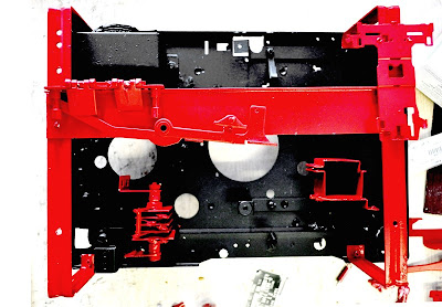


(pulling a radio apparatus back together for tectonic inspiration)

Thursday 19 April 2012

Building schematics


After dismantling the apparatus and translating all the parts into analogous architectural schematics I tried to build my own - Finnish Institute Schematics.

The diagrams you see above show:

1) Architectural interpretation of transmitter, receiver and amplifier as places where energy is managed - either released, absorbed or modified. Energy in Finnish Institute is the moving part of the building, the blood of this organization - creative potential of people and collaborations.

2) Established the ultimate functional difference between transmitter and receiver by providing different spaces either feeding or being fed energy (last diagram) and made it into a building diagram. Amplifier is used as a break point where the energy 'leaks' to outside therefore the amount of it is modified more rapidly.

3) Translated the functional performance of a radio circuit which is then used to define the private (receiver) and public (transmitter) sectors.

Saturday 7 April 2012

ANALOG


Just an update that the process of dismantling an apparatus has been going on without the notice on blog. A beautiful model, no glue just studs and screws and too many wires inside. So you may guess that it took quite a while to take it a-part. The most interesting part for me were the circuit board showing all the welded nodes of interconnections (architecturally speaking, it is almost a literal representation of points where collaboration happens collaboration), and also the old-school rectifier (in the image of distributed parts in red), coils and wire systems.

Not to mention a beautiful box it all came in.

Here's my old MAYFAIR reel-on-reel for you: